Real Robots
Make some cool stuff

Robby the Robot v2

Coding 4: Inputs


We are absolutely flying now, let's learn about inputs.

Inputs are the opposite of outputs, this time our microcontroller pins are going to listen to the outside world to get information, rather than send it.

Let's start with a new, empty program.


    void setup() {    

    }
    
    void loop() {
             
    }
                

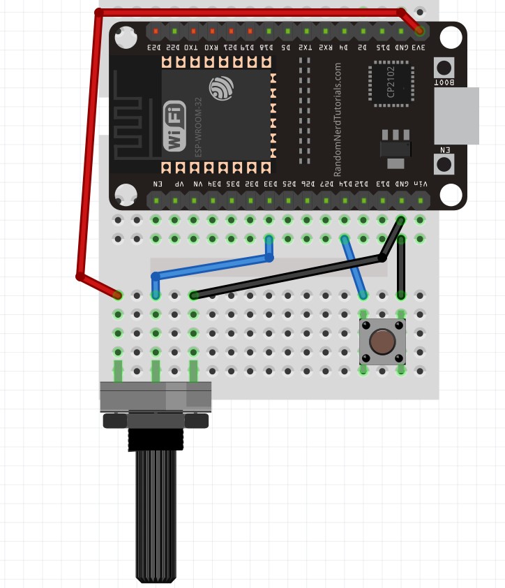
Let's plug in a button first so we have something to test.

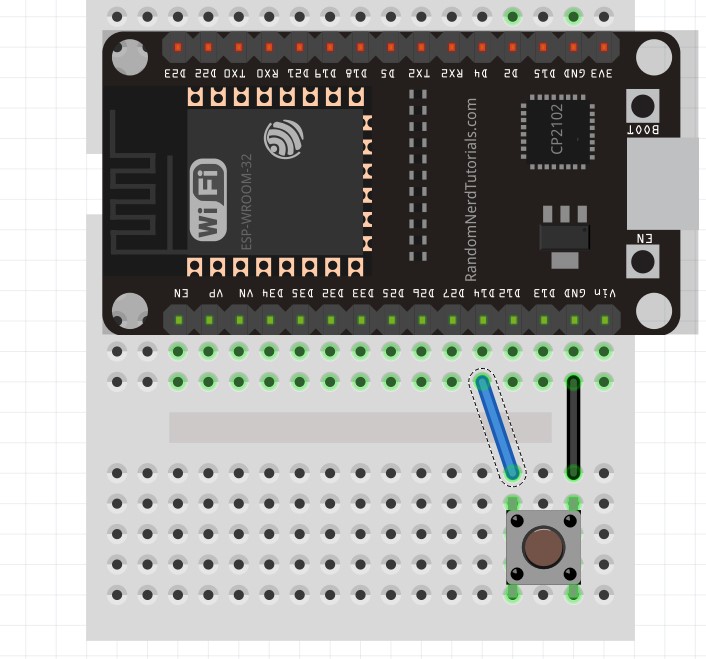
With this button, the left two pins are disconnected from the right two pins until the button is pushed, then they are connected.

So when the button is pushed we have a connection from D14 to GND.

Just like with outputs, there's two things we need to do.

pinMode(14, INPUT_PULLUP);

This sets pin D14 to INPUT mode, the PULLUP means that it's set to be usually HIGH. When we give it path to GND the 3.3v HIGH will flow away to GND and the pin will see 0v.

digitalRead(14);

This tells us what pin D14 can see, if it sees 3.3v then it will give us a "1", if it sees 0v then it will give us a "0".

Enter the following code, note that we need to use Serial to tell us what is happening, putting digitalRead(14) in the Serial.println() function will send that to us.

    
    void setup() {    
        Serial.begin(115200);
        pinMode(14, INPUT_PULLUP);
    }
    
    void loop() {
        Serial.println(digitalRead(14)) ;          // check pin 14/send to Serial
        delay(10);                                 // wait 0.01 sec
    }
                

Now press the UPLOAD button, connect the Serial Monitor and see what happens when you push the button.

Since the digitalRead() returns a 1 or 0 we can get fancy.

    
    void setup() {    
        pinMode(2, OUTPUT);
        pinMode(14, INPUT_PULLUP);
    }
    
    void loop() {
        digitalWrite(2, (digitalRead(14)) ;        // check pin 14/set pin 2 the same
        delay(10);                                 // wait 0.01 sec
    }
                

Can you guess what is happening here?

We are setting up our built in LED again on pin 2. But now instead of setting it 0 or 1 ourselves, we take the value from the button. So now we can control the LED with our button.

Potentiometers

Let's try a different kind of input. Instead of just on or off, this control changes as you turn, giving between 0 and 3.3v as you go.

The potentiometer has 3 pins, the left goes to 3.3v, the right goes to GND and the middle is our input.

Let's plug our input into pin 33.

Just like before, we set the pin to INPUT_PULLUP mode.

pinMode(33, INPUT_PULLUP);

But this time we use analogRead(), which gives us a value from 0-4096 from a 0v-3.3v input.

analogRead(33);
    
    void setup() {    
        Serial.begin(115200);
        pinMode(33, INPUT_PULLUP);                  // set pin 33 to INPUT mode
    }
    
    void loop() {
        Serial.println(analogRead(33)) ;            // check pin 33/send to Serial
        delay(10);                                  // wait 0.01 sec
    }
                

Now press the UPLOAD button, connect the Serial Monitor and see what happens when you turn the pot.

CHALLENGE

Make the built in LED flash faster/slower when the pot is turned.

HINT: Copy the code from our LED flashing into the latest code.

HINT: How can you take the 0-4096 value from the pot and use it to change the flashing speed?

PREV NEXT